LED Head - Leitz Focomat V35
 Fig. 1 - LED Light Mix box, build into the Focomat V35 head
 Fig. 2 - LED Light mix box components (Box, 2x additional diffusors,
aluminum based LED PCB). LEDs not yet fitted
Fig. 2 - LED Light mix box components (Box, 2x additional diffusors,
aluminum based LED PCB). LEDs not yet fitted
 Fig. 3 - LED Light mix box assembled
 Fig. 4 - LED Light mix box of the Focomat V35 (green LEDs active)
 Fig. 5 - LED control unit, replacing the Focomat V35 bulb holder
 Fig. 6 - The Focomat V35 LED control board with four 700mA constant current drivers (MeanWell LDD-700L)
and the ESP8266 board
Fig. 6 - The Focomat V35 LED control board with four 700mA constant current drivers (MeanWell LDD-700L)
and the ESP8266 board
The Focomat V35 enlarger originally uses halogen bulbs (e.g. Philips 13139), which are no longer in production
and therefore are hard to get a hand on. Due to a very special angle of radiation, standard bulbs,
which fit the bulb holder, result in a rather pure illumination.
To overcome this issue, a LED head has been developed together with a LED control unit. The necessary
LEDs have been placed into the original light mix box, as shown above. The LED control unit fits into
the Focomat V35 enlarger's bulb compartment. The darkroom timer and the LED control unit communicate via a
WiFi-network. Power is supplied to the LED control board using the original transformer, which offers
more than enough power for the LEDs.
One goal of the development was to remove the need for any addtional wiring. The control unit
receives exposure commands from the darkroom timer using the MQTT protocol.
Fig. 1 shows the build in LED light mix box. The compartment for the color filter unit remains empty.
The wiring to the LED control board goes into the compartment where the original bulb unit was placed
(which is rather easy to remove).
In order to fit the LED PCB and the additional diffusors it is necessary to cut out some foam parts of
the original light box. You can see this in Fig. 2. Fig. 3. shows the assembly.
For a first test, the LED light box is supplied with a constant current of 700mA, powering the two
green LEDs (each 3W). We will later see, that the resulting light is very homogeneous. Mmy initial
concern was, that the two LEDs are not able to homogenously distribute the light. Hence I added two diffusors
right after the LED board, which seem to do the trick). The real big advantage of the "2 times 3W" LED approach
is the overall price of the LED head (8 LEDs each < $1) and the rather low heat dissipation. The 2mm thick LED
aluminum PCB seems sufficient to dissipate the power, when used in normal darkroom operation. Nevertheless, there is enough space in the light box to include also a nicely sized heatsink.
The LED board contains red (620-630nm), white (4000-4500k), blue (420-430nm) and green (520nm) LEDs. Therefore, it is possible to use it
for variable contrast papers - avoiding the necessity of "external" filters. The LEDs are controlled using
an ESP8266-based, Wifi-enabled microcontroller. I decided to go for a wireless connectivity, as
it avoids a cable mess in the darkroom ;) The exposure requests are send as "exposure jobs" from the darkroom timer to the LED controller.
Therefore, even in the event of an interrupted WiFi connection after the exposure has started, the exposure will be completed correctly
as the LED controller is handling the received "exposure job" by itself.
One additional advantage of using LEDs compared to standard bulbs is the absence of UV light, which can have negative impacts on the print sharpness.
Overall it can be stated: As suitable LEDs have become available in the last years, standrd light sources (tungsten bulbs, halogen bulbs) have become obsolete for their
usage in enlargers. LEDs are more durable, expose less power dissipation, are cheap and show just the right light spectrum for multigrade paper.
Note: I reached out to Iford technical support to find out more about the wavelength sensitivity regarding their Multigrade papers.
Here is the basic info: Maximum green sensitivity is around 530nm. Hence, the green light should be within 530 +-5nm. The blue sensitivity is much broader and less critical.
Suggestion is to try 450nm +-10nm.
As I did not have this information at the start of the development, I selected LEDs which are slightly off these values (blue 420-430nm and green 520nm). However, later paper tests have shown
that even with this selection almost the complete paper ISO R range can be used.
Grade Controller and Darkroom f-Stop Timer - Focometer
 Fig. 7 - An original Leitz Focometer unmodified with its original probe
 Fig. 8 - The modernized Focometer
 Fig. 9 - The new PCB for the Focometer
I decided to reuse the enclosure of an old Leitz Focometer (those where build in the late 70s / early 80s).
I do actually like its design with big sturdy buttons.
However, its electronics are outdated and had to be completely removed. The only remaining parts
are the buttons, switches and the 7 segment display. Due to simplicity, I opted to place an
RaspberryPI4 as the computational main unit - which is a bit of an overkill but keeps the development time low.
A new PCB was developed that fits perfectly into the Focometer and additionally offers the following
connections/compontents:
- 2.4 inch TFT-Display (320x240 pixels)
- 3 Bluetooth modules (HC05, BLE, Microchip)
- 21 LEDs (replacing the paper index switch)
- 2 Rotary switches with additional push button functionality
- 3 Push buttons
- 40 pin RaspberryPI connector
The internal PCB does not only hold the above mentioned new components but also includes the
circuits that generated the two required supply voltage levels (5V/4A and 3.3V/1.5A). The unit is powered by
an external switching power supply, operating at 7.5V.
Currently supported modes of operation:
- Main exposure menu (adjust ISO R range and exposure time in terms of f-stops)
- Red light activation
- Focus light and measurement mode (probe connection via Bluetooth, measuring film density and base time for exposure)
- Configuration (Paper selection, global dimming factor)
To be implemented are functions like:
- Wirelessly reading in the test wedge data and reflection density measurements for calibration of new paper types/batches
- Dodging and burning support
- Test strip mode
Here you can see it in action: Video (poor quality though).
Bluetooth Measurement Probe (Light meter)
 Fig. 10 - Unpopulated PCB and the ProbeNG prototype
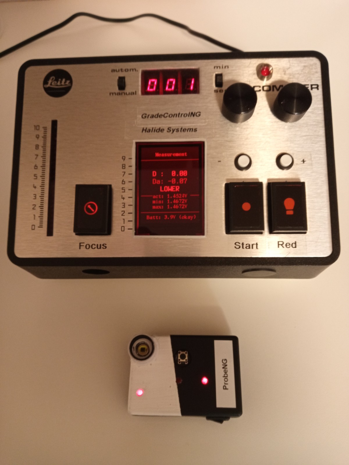 Fig. 11 - ProbeNG - Size comparison
 Fig. 12 - ProbeNG - popluated PCB
In order to measure the film density as well as the required exposure timing, a new sensor
probe has been developed - with the aim to provide excellent measurement accurracy as well as to wirelessly connect
the probe to the darkroom timer.
To the best of my knowledge this is the only probe without the need having a wired connection to a measuring unit.
The probe is shown in the figures 10 and 11.
The probe was designed around a logarithmic OpAmp (Texas Instruments ADL5304 - 200dB bandwidth! - i.e. 1pA to 10mA), used to measure
the current of a BPW21R photo diode.
The sensed current is converted into a voltage (200mV/dec, and the measured voltage is directly proportional
to the density) which is measured using an highly accurate 16-bit ADC (TI ADS111x in single-ended mode - which is kind of an overkill at 2000mV / 32768 = 0.061mV/bit,
resulting in a density resolution of roughly 0.003 per bit over the full 200dB range).
An ESP32 development board reads the ADC values and
transmits the data via Bluetooth to the darkroom timer. Power is supplied using a 500mAh LiPo battery (approx. enough energy to work for 1h).
The battery voltage is converted into 5.0V using a boost converter. The LiPo battery is charged via micro USB.
(Hint: Special care was taken during the PCB design to avoid leakage currents into the OpAmp inputs. This is particular
important to measure low light levels accurately.
Here the photo diode current is around 10-100pA ... a leakage current in this range can easily be generated by a
voltage drop towards the OpAmp inputs and the PCB base material resistance. E.g. 5V/100p = 50GOhm!
To-do: Develop an Android app that displays the measurement values. In this way, work without the Focometer timer would be possible, too.
Wireless Darkroom Safe Light - Ilford SL1
 Fig. 13 - Darkroom safe light with wirless antenna (switches to
select the LED color)
Fig. 13 - Darkroom safe light with wirless antenna (switches to
select the LED color)
 Fig. 14 - Darkroom safe light PCB (attached ESP01) and LED
As the darkroom timer is already logged into a wireless network to communicate with the
Focomat V35 enlarger electronics (LED head), it is possible to also bring the darkroom safe lights into
the same network. In this way, they can be turned on and off from the darkroom timer without
the need of additional wiring. Figure 12 shows an Ilford SL1 from which the original bulb has been removed.
It has been replaced using orange and red LEDs (Peak wavelengths Orange:600-605nm and Red: 625-630nm). The
used LED is selected by some switches.
Reflection Densitometer - Techkon RT112
 Fig. 15 - The new PCB produced to fit into the original enclosure
Update of an Techkon RT112. Basically only the enclosure was reused. Sensor element is a
TSL2591, which is connected via I2C to an ESP32-based development board. An .49inch OLED
display is used for reading out the measured density. Additionally the measurements are
sent to the UART interface, so they can be transferred into a PC terminal directly.
A white 3mm LED replaces the old bulb. The required constant current is stabilised using
a simple two NPN-transistor circuit.
Transmission Densitometer - Tobias TCX
 Fig. 16 - Enclosure Tobias TCX densitometer
 Fig. 17 - Update electronics ESP32-based
 Fig. 18 - Replacing the halogene bulb using an 1W white LED
Although I usually measure the film density with the darkroom timer
probe, a densitometer is a nice-to-have tool. It allows you to measure the film
density during daylight, very quickly. Hint: Using the darkroom timer probe, of
course, ensures that you are measuring even side-effects that impact the light. Those effect
are not included when using the transmission densitometer.
I did purchase a Tobias TCX transmission densitometer on the second-hand-market for
around $30. And it actually was still working. However, as it lacks some communication
interface, which would allow to read-in the measurement values directly into a
spreadsheet, I decided to update it. The update includes a 16x2 LCD display, a ESP32
development board (offering Bluetooth as well as Wifi connectivtiy), LED as transmission
light source and an ams TSL2591 light sensor.
Film processor
 Fig. 19 - Simple film processor
 Fig. 20 - The step motor controller
 Fig. 21 - Unpopulated PCB with space an Arduino Nano
I find the film development step rather boring - Aggregation every 60 seconds and being worried not to miss any of the cycles.
The simple construction shown in Fig. 18 solves the problem for me. The aggregation during the development is now done automatically. While
stopping and fixation can still be done manually. But these two steps are less delicate and not so time consuming.
Here you can see it in action: FilmProcessor
Thermometer and Timer unit
 Fig. 22 - Thermometer and timer
Before developing the film processor, I had already build a combined thermometer and timer unit.
The thermometer is based on a DS18B20 1-wire thermometer with an accuracy of +-0.5°C (3-sigma value from the MAXIM datasheet).
Although this accuracy is not really sufficient for the film development, it represents mainly a
static offset (at a given temperature point) from the actual temperature. So once you have
measured this offset (at close to 20°C), it can be used as a rather accurate instrument to
determine the temperature of the developer.
(More background info on the DS18B20 accuracy can be found
here.)
I use this device as my main lab thermometer. Additionally, I have three more DS18B20 sensors which
can be attaced to the unit. Having documented the offsets of each device, I can easily replace the main
sensor...and I would not need to re-calibrate my development times.
Important note: Please take care when buying DS18B20 sensors online. Most of the "DS18B20s" which you can by online are fake/replicas of the Maxim original!
If you want to be sure to by an original version, go for the big distributes and no dogy sources. In case you have already purchased some sensors and you
want to find out if those are originals...there is a Arduino library to identify the fakes. Look for "counterfeit_DS18B20" on the net.
Coming to the timer part: The "free-running" timer starts upon power-on or reset form zero. It generats a beep every minute - so none of the aggregation
cycles can be missed. Here is a short demonstration video.
Bath timer unit
 Fig. 23 - Bath timer
During the development of the prints, the paper has to stay in the various baths for some predetermined time.
I usually use four baths. Namely, developer, stopper, fixation 1 and fixation 2. Based on the four baths I have
implemented a small timer unit, that displays four "free" running timers. Each timer can be resetted by
one of four push buttons. The LCD display uses a darkroom safe red backlight.
Calibration: Paper and LED head
 Fig. 24 - Ilford RC Deluxe New (ISO R 55-160)
 Fig. 25 - ADOX EasyPrint RC (ISO R 73-176)
 Fig. 26 - First test result - it works:)
Toward the first picture it is necessary to calibrate the used papers together with the
new LED light source. To Do: Outline the procedure.
Calculating the possible gradations shows that an ISO R range from 55 to 160 has been
achieved on the "Ilford Deluxe New" ... almost matching the datasheet values of Ilford :) However, a green LED of 530nm instead of 520nm will be used in my next tests.
Camera Shutter Checker
 Fig. 27 - Shutter Checker PCB
 Fig. 28 - Measurement setup incl. a laser pointer
I own a couple of cameras without electronically controlled shutter timing - that is, these cameras are working purely mechanically.
In order to check if camera shutter fulfills the correct timing, the Camera Shutter Checker has been developed.
As shown in the measurement setup, the shutter checker uses a photo diode to detect when light is passing through the opened shutter.
As the used photo diode exhibits a directional characteristic, it is important for an accurate measuement to restict the light to a "single"
focused beam. This can be achieved, for example, by using the setup shown in Fig. 27. As light source a "standard" laser pointer can be used and the photodiode is placed within a tube.
Additionally, a carton with a pin-hole is placed infront of the tube.
Without such focused light beam, the measurement will become inaccurate at short shutter timings. Anyway, when interpreting the measurement results it is important to understand the limitations
of the shutter time measurement using a photodiode. Due to the size of the active sensor element, their exists an error that is proportinal to the ratio of sensor width and shutter slit width.
A way to get around this problem is to check the actual reverse current level of the photodiode to detect when the sensor area is completely exposed to light or partially covered.
Mmmhhh...more work to do.
Here is a short demonstration video.
And here are the schematics.
Here is the SW.
Simple LED Darkroom light bulb replacement - Osram Duka 10
 Fig. 29 - Osram Duka 10 and simple schematics
I recently got hold of a Osram Duka 10 darkroom safe light with a broken blub (I like its design). As the special sodium-vapor blub is not easy to replace (or rather expensive),
I ended up installing a single high-power red LED together with a constant current source (MeanWell LDD).
The whole setup costed around 6€ - and now it can be used again.
BTW, many old darkroom lights use standard 15W tungsten bulbs and therefore require an appropriate filter. Accordingly, the remaining emitted light is rather weak. LEDs with a rather limited
emitted wavelength band are far more suitable for the darkroom.